

- Details
- Reviews
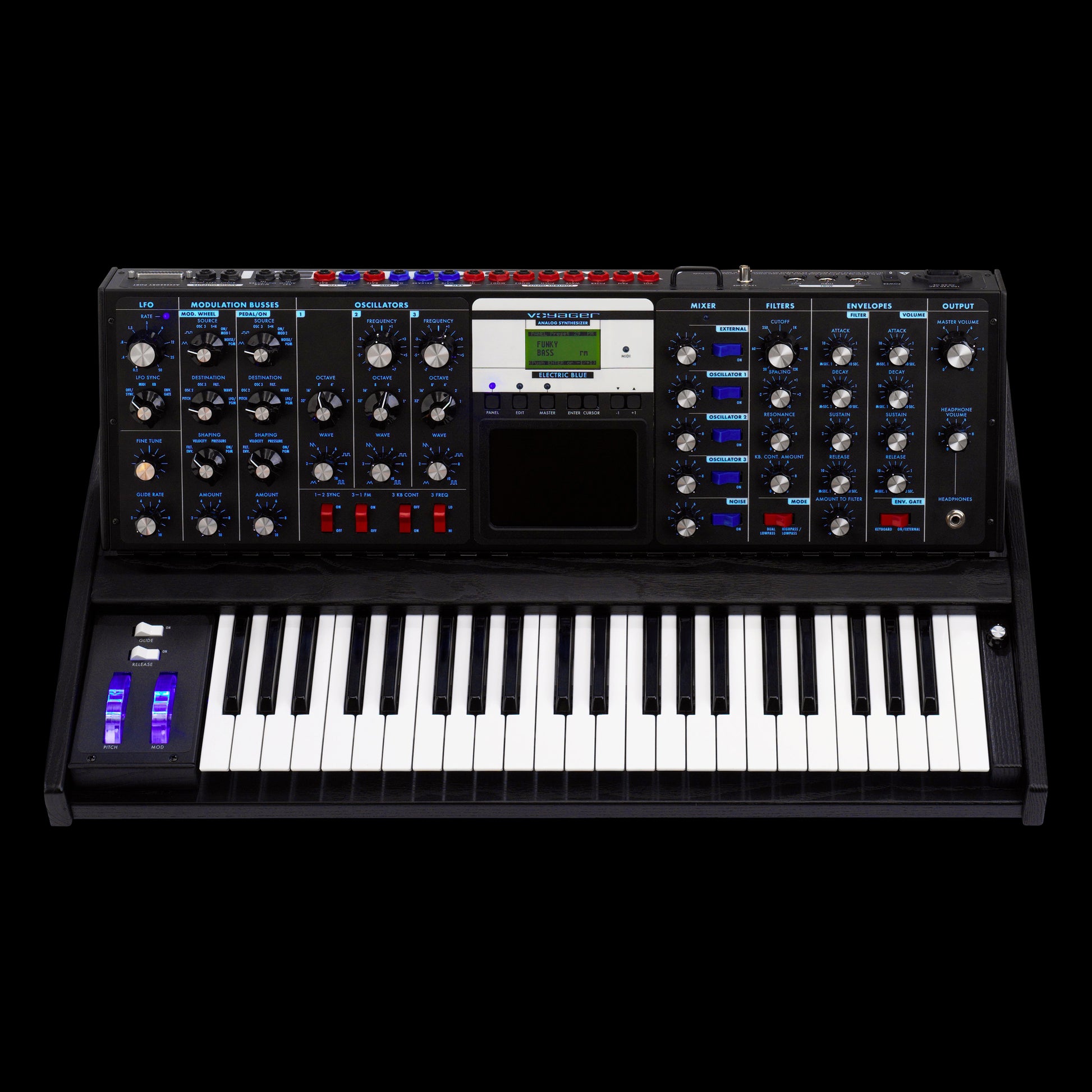
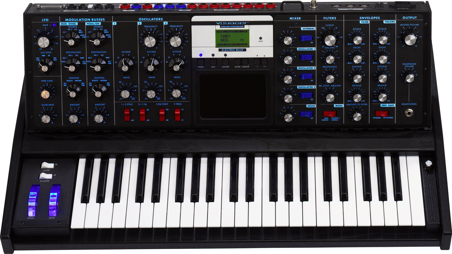
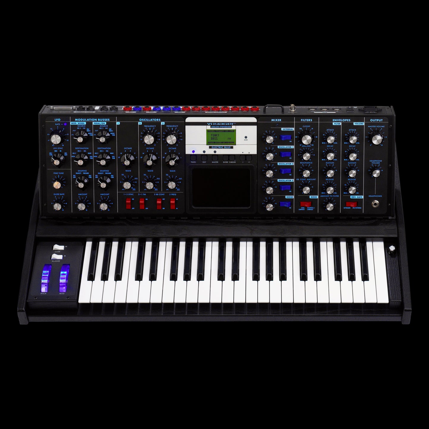
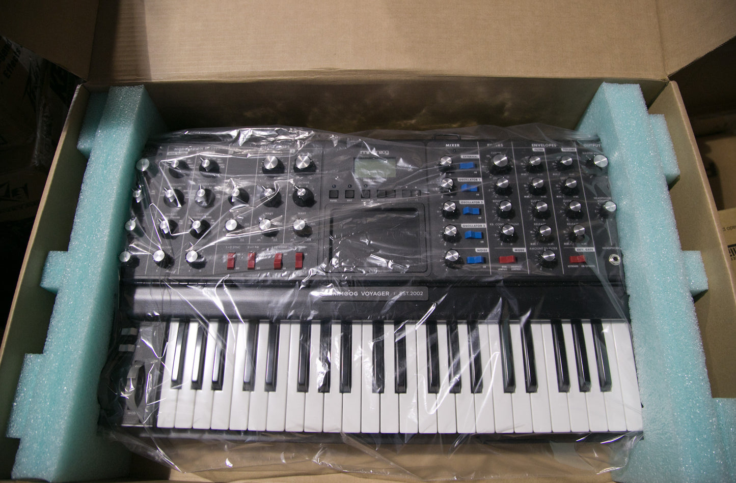
Moog Minimoog Voyager Electric Blue
It's the Voyager with all the sonic quality one would expect plus a finish that rivals its sound.
Played by the likes of Jesse Carmichael of Maroon5 and Printz Board of the Black Eyed Peas. The Electric Blue Voyager is housed in a fractal blue solid ash cabinet. At first it looks black but as one draws near the fractal blue flecks pop out in an eye catching display. Combine this with the stunning look of the electric blue back lit panel, new blue LED's, and some new killer patches and you have an instrument you will be proud to play for a lifetime.
Features and Technical Specifications
The MINIMOOG VOYAGER Synthesizer is a monophonic (one note at a time) analog performance synthesizer. It incorporates virtually all of the sound resources and functions of the original Model D Minimoog, which was produced by Moog Music, Inc. from 1970 to 1982. It has many new additional features, including a three dimensional touch surface, MIDI IN and MIDI OUT implementation, extensive patching facilities, and a large number of new panel features.
The signal path starts with a bank of three wide-range, high-stability voltage controlled oscillators, one noise source, and one audio preamplifier for externally-applied audio signals. The sound modifiers are two Moog filters and one stereo VCA (Voltage Controlled Amplifier). Modulation sources are two ADSR (Attack Decay Sustain Release) envelope generators and one multiwaveform LFO (Low Frequency Oscillator).Control devices include a 44-key keyboard with velocity and afterpressure outputs, pitch bend and modulation wheels, a three dimensional touch surface, and many control/pedal input jacks.
The MINIMOOG VOYAGER has a hinged, multi-position panel and a solid hardwood cabinet. The power supply accepts any power voltage from 100 volts to 240 volts.
Oscillators Module
Three wide-range, high stability VCO's (Voltage Controlled Oscillators) with continuously-variable waveforms.
* FREQUENCY controls (2) vary the frequencies of Oscillators #2 and #3 over a +/-7 semitone range with respect to Oscillator #1.
* OCTAVE selectors (3) set the frequency ranges of the oscillators in six octave steps.
* WAVE controls (3) provide continuous control over the waveforms of the oscillators, from triangular, to sawtooth, to square, to narrow rectangular.
* 1-2 SYNC switch synchronizes the Oscillator #2 waveform to the frequency of Oscillator #1, for dramatic timbral effects.
* 3-1 FM switch provides linear frequency modulation of Oscillator #1 by Oscillator #3.
* 3 KB CONT switch disconnects Oscillator #3 from control by the keyboard, thereby enabling it to function as a drone.
* 3 FREQ switch lowers the frequency of Oscillator #3 into the sub-audio range, thereby enabling it to function as a low frequency audio or modulating oscillator.
Mixer Module
Five-input mixer for combining the audio sources prior to filtering.
* Input Level controls (5) adjust the relative levels of the oscillator, noise, and external audio input signals.
* Input switches (5) enable the player to quickly switch individual audio signals in and out.
* External Level LED enables the player to set the correct external audio signal level.
Filters Module
Dual mode filter module includes dual lowpass and highpass-lowpass filtering. Dual lowpass mode consists of two Moog lowpass-resonant filters in parallel, one per output channel. Highpass-lowpass mode consists of Moog lowpass filter in series with a highpass filter.
* CUTOFF control sweeps the frequencies of both filters throughout the audio range.
* SPACING control sets the spacing between the frequencies of the two filters, over a +/-3 octave range.
* RESONANCE control adjusts the resonance of both filters, from none (pure lowpass response) to filter oscillation.
* KB CONT AMOUNT control sets how much the filters open and close as the player presses different keys on the keyboard.
* Dual Lowpass/Highpass-Lowpass switch selects between dual lowpass operation or highpass-lowpass operation.
Envelopes Module
The Envelopes Module generates two wide-range ADSR (Attack Decay Sustain Release) envelopes. The Filter Envelope sweeps the filter and is available for modulation shaping. The Volume Envelope shapes the overall volume.
* ATTACK controls (2) determine the attack times of the envelopes.
* DECAY controls (2) determine the decay time constants of the envelopes.
* SUSTAIN controls (2) determine the sustain levels of the envelopes.
* RELEASE controls (2) determine the release time constants of the envelopes.
* AMOUNT TO FILTER control determines how much the filter envelope will open and close the filter, from full negative (inverted envelope) to full positive (non-inverted envelope).
* ENVELOPE GATE SWITCH selects whether the envelopes will be triggered by the keyboard, on , or by an externally-applied gate.
LFO Module
Low Frequency Oscillator generates triangular, square, Sample & Hold, and smoothed Sample & Hold waveforms for use as modulating signals.
* RATE control sets the LFO rate over the range 0.2 Hz (one cycle every five seconds) to 50 Hz (fifty times a second).
* SYNC selector selects LFO synchronization source to be from the keyboard gate, external envelope gate, external gate, or off (no synchronization).
* RATE LED provides visual indication of the LFO rate.
Modulation Busses Module
Selects the sources, destinations, and shaping signals for the MOD WHEEL bus and the EXT PEDAL/ON bus.
* SOURCE selectors (2) selects the modulation source from the LFO triangle or square waveforms, Oscillator# 3, sample and hold, the external modulation input (MOD2) or noise.
* DESTINATION selectors (2) selects the modulation destination from all the audio oscillators, just Oscillator #2, just Oscillator #3, the filter cutoff frequencies, the oscillator waveforms, or LFO Rate.
* SHAPING selectors (2) selects the key pressure signal, filter envelope, note-on velocity or on to shape the modulation signal on that bus.
* AMOUNT controls (2) sets the overall modulation amount for each bus.
Output Module
* MASTER VOLUME control sets the overall level of the instrument's audio outputs.
* HEADPHONE VOLUME control sets the overall level of the headphone output.
* HEADPHONES jack: 1/4" tip-ring-sleeve phone jack for regular headphones.
Glide and Fine Tune Module
* GLIDE varies the speed at which the keyboard voltage changes, from instantaneous to several seconds.
* FINE TUNE adjusts the overall tuning of the instrument.
V 3.3 Software Capabilities
Voyager Software developed by Rudi Linhard of Lintronics.
www.lintronics.biz
* FRONT PANEL STORAGE AND RECALL: Except for the Fine Tuning control, the settings of all front panel controls, selectors, and switches are stored in the nonvolatile digital memory. A total of eight hundred ninety-six front panel presets may be stored for instant recall.
* TRANSMISSION AND RECEPTION OF KEYBOARD DATA VIA MIDI: Polyphonic note-on and note-off with velocity can be transmitted (Note numbers 53-96).The Voyager responds to note-on (0-127) messages monophonically with user defineable note priority. The Voyager's Front Panel Controls transmit and respond to MIDI CCs. Please refer to the Voyager User's Manual for a list of the Front Panel Controls and their corresponding MIDI CC#s.
* UPLOADING AND DOWNLOADING OF PRESETS VIA MIDI: Individual Presets or whole Preset banks may be uploaded and downloaded via MIDI System Exclusive.
* UPDATING OF OPERATING SOFTWARE VIA MIDI: The instrument's operating software can be updated via MIDI files (.syx Sysex files) which will be available on Moog Music's web site in the Support Docs and Software section.
PANEL MODE FEATURES: Panel Mode features include Compare, Quick Mode (Preset changes with +/-1 buttons), Parameter Display (view stored paramter value, current parameter value), and enable/disable preset Master and Headphone Volume.
EDIT MODE FEATURES: Related to Preset Parameters not on Front Panel, these include: Compare tp Preset, Recall last Sound, Real Panel Control, Pitch Bend Amount, Programmable Mod Buss Sources, Destinations and Shaping, Keyboard and Trigger Modes, FIlter Pole Select, Envelope Gate Source, Touch Surface Destinations, Touch Surface Memory, Pot Mapping Mod. Matrix, LFO MIDI Clock Divider, Initialize Parameters, Preset Name, and Save Preset.
MASTER MODE FEATURES: Global Settings and functions for the Voyager include: LCD Contrast, MIDI Local Kbd. On/Off, MIDI Merge, MIDI Program Change On/Off, MIDI In/Out Channel, MIDI In/Out On/Off, Send Panel Sound, Send All Presets, Receive Presets, SysEx Device ID, Transpose In/Out, MIDI Key Order, Velocity Curve, Copyright Info, Software Version, Send System ROM, Send Boot System, Receive Update.
Player Control Interfaces
* 44 KEY KEYBOARD produces Pitch, Gate, Velocity, and Pressure control outputs.
* WHEELS: Pitch Wheel bends pitch over a range of up to +/-1 octave. Mod wheel controls the gain of the MOD WHEEL bus.
* GLIDE and RELEASE switches provide real-time on-off control over the glide and release functions.
* THREE DIMENSIONALTOUCH SURFACE provides three continuously-variable control signals which are derived from the up-down and left-right position of the player's finger, and the amount of area with which the player makes contact to the surface.
Rear Jack Panel
Listed below:
Pedal/Control Inputs
These ten jacks have red nuts. They accept either expression pedals or control voltages, and control the following performance parameters:
* VOLUME
* PAN
* FILTER CUTOFF
* WAVEFORM
* PITCH
* MOD2 - EXTERNAL MODULATION SOURCE
* MOD1 - EXTERNAL CONTROL OF THE PEDAL MOD. BUS
* SAMPLE AND HOLD IN
* ENVELOPES RATE
* LFO RATE
Accessory Port
The Accessory port delivers
the Control Voltage and gate
signals generated inside the Voyager to a standard DB-25
connector. This is designed for use with the VX-351 Voyager CV Expander.
LFO Sync
A footswitch or gateapplied to this input will reset the LFO waveform to the beginning of its cycle.
Envelopes Gate
A footswitch or gate applied to this input will start the envelopes.
Sample and Hold Gate
A gate signal applied to this jack will trigger a new sample and hold voltage.
Release
foot switch plugged into this jack will have the same effect as depressing the corresponding switch on the left hand controller panel.
Mixer Ext In
Plug any instrument-level or line-level audio signal in this jack to combine with the oscillator and noise signals prior to filtering.
Mix Out/Filter Audio In
The output of the audio mixer appears here, before being fed to the filter. Normally, the Mixer output is bridged directly to the filter input. If you plug something into this jack, that breaks the normal connection. Using a standard insert cable (1/4" TRS plug to two 1/4" TS plugs) this jack can be used as an effects loop for external processing of the Mix before it goes to the filter.
Left(Mono) and Right Audio Outputs
The audio outputs are 1/4 " unbalanced outputs. The two output channels are summed to mono when only the left(mono) output is used.
12V Lamp
The BNC Lamp Socket provides 12VDC for a gooseneck lamp.
MIDI In, Thru, and Out Connectors
Standard MIDI connectors for interfacing with other MIDI gear.
Power Input
The Voyager's power input accepts a standard power cable. The Voyager works from 100-250 VAC, 50-60 Hz.
Dimensions and Weight
30 1/2" Wide X 18" Deep X 3" High (when flat) 12" High when fully upright.
40 lbs.
| Product Name | Moog Minimoog Voyager Electric Blue |
|---|---|
| Brand | Moog |
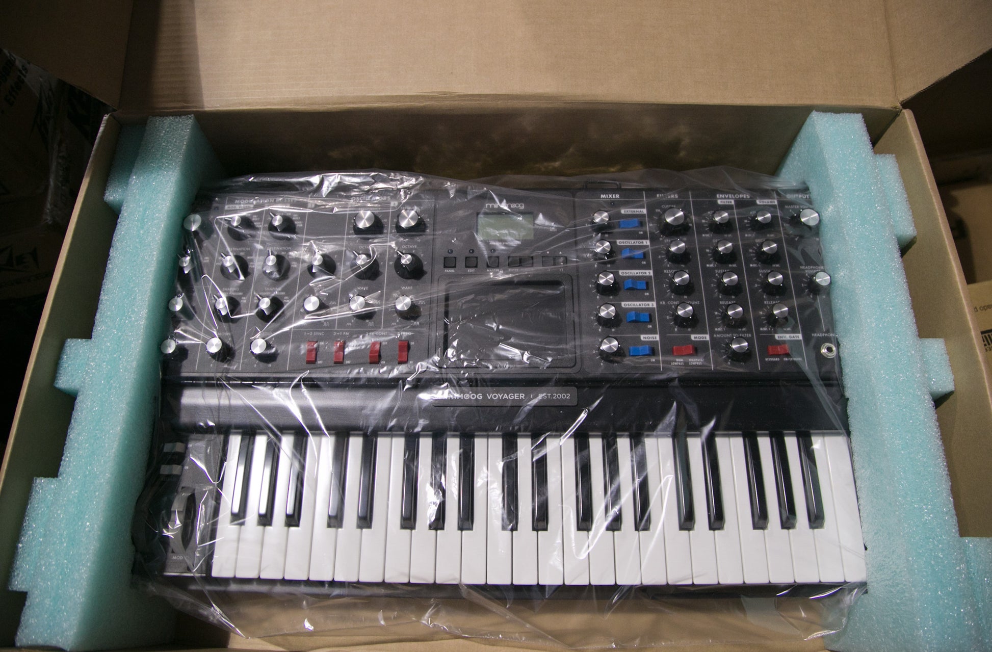
| Condition | New |
| MPN | VY-MIN-014-EBB |
| UPC | 889406080546 |
| Shipping Option | Free Shipping to the Continental U.S. |
Moog Minimoog Voyager Electric Blue
Details
Moog Minimoog Voyager Electric Blue
It's the Voyager with all the sonic quality one would expect plus a finish that rivals its sound.
Played by the likes of Jesse Carmichael of Maroon5 and Printz Board of the Black Eyed Peas. The Electric Blue Voyager is housed in a fractal blue solid ash cabinet. At first it looks black but as one draws near the fractal blue flecks pop out in an eye catching display. Combine this with the stunning look of the electric blue back lit panel, new blue LED's, and some new killer patches and you have an instrument you will be proud to play for a lifetime.
Features and Technical Specifications
The MINIMOOG VOYAGER Synthesizer is a monophonic (one note at a time) analog performance synthesizer. It incorporates virtually all of the sound resources and functions of the original Model D Minimoog, which was produced by Moog Music, Inc. from 1970 to 1982. It has many new additional features, including a three dimensional touch surface, MIDI IN and MIDI OUT implementation, extensive patching facilities, and a large number of new panel features.
The signal path starts with a bank of three wide-range, high-stability voltage controlled oscillators, one noise source, and one audio preamplifier for externally-applied audio signals. The sound modifiers are two Moog filters and one stereo VCA (Voltage Controlled Amplifier). Modulation sources are two ADSR (Attack Decay Sustain Release) envelope generators and one multiwaveform LFO (Low Frequency Oscillator).Control devices include a 44-key keyboard with velocity and afterpressure outputs, pitch bend and modulation wheels, a three dimensional touch surface, and many control/pedal input jacks.
The MINIMOOG VOYAGER has a hinged, multi-position panel and a solid hardwood cabinet. The power supply accepts any power voltage from 100 volts to 240 volts.
Oscillators Module
Three wide-range, high stability VCO's (Voltage Controlled Oscillators) with continuously-variable waveforms.
* FREQUENCY controls (2) vary the frequencies of Oscillators #2 and #3 over a +/-7 semitone range with respect to Oscillator #1.
* OCTAVE selectors (3) set the frequency ranges of the oscillators in six octave steps.
* WAVE controls (3) provide continuous control over the waveforms of the oscillators, from triangular, to sawtooth, to square, to narrow rectangular.
* 1-2 SYNC switch synchronizes the Oscillator #2 waveform to the frequency of Oscillator #1, for dramatic timbral effects.
* 3-1 FM switch provides linear frequency modulation of Oscillator #1 by Oscillator #3.
* 3 KB CONT switch disconnects Oscillator #3 from control by the keyboard, thereby enabling it to function as a drone.
* 3 FREQ switch lowers the frequency of Oscillator #3 into the sub-audio range, thereby enabling it to function as a low frequency audio or modulating oscillator.
Mixer Module
Five-input mixer for combining the audio sources prior to filtering.
* Input Level controls (5) adjust the relative levels of the oscillator, noise, and external audio input signals.
* Input switches (5) enable the player to quickly switch individual audio signals in and out.
* External Level LED enables the player to set the correct external audio signal level.
Filters Module
Dual mode filter module includes dual lowpass and highpass-lowpass filtering. Dual lowpass mode consists of two Moog lowpass-resonant filters in parallel, one per output channel. Highpass-lowpass mode consists of Moog lowpass filter in series with a highpass filter.
* CUTOFF control sweeps the frequencies of both filters throughout the audio range.
* SPACING control sets the spacing between the frequencies of the two filters, over a +/-3 octave range.
* RESONANCE control adjusts the resonance of both filters, from none (pure lowpass response) to filter oscillation.
* KB CONT AMOUNT control sets how much the filters open and close as the player presses different keys on the keyboard.
* Dual Lowpass/Highpass-Lowpass switch selects between dual lowpass operation or highpass-lowpass operation.
Envelopes Module
The Envelopes Module generates two wide-range ADSR (Attack Decay Sustain Release) envelopes. The Filter Envelope sweeps the filter and is available for modulation shaping. The Volume Envelope shapes the overall volume.
* ATTACK controls (2) determine the attack times of the envelopes.
* DECAY controls (2) determine the decay time constants of the envelopes.
* SUSTAIN controls (2) determine the sustain levels of the envelopes.
* RELEASE controls (2) determine the release time constants of the envelopes.
* AMOUNT TO FILTER control determines how much the filter envelope will open and close the filter, from full negative (inverted envelope) to full positive (non-inverted envelope).
* ENVELOPE GATE SWITCH selects whether the envelopes will be triggered by the keyboard, on , or by an externally-applied gate.
LFO Module
Low Frequency Oscillator generates triangular, square, Sample & Hold, and smoothed Sample & Hold waveforms for use as modulating signals.
* RATE control sets the LFO rate over the range 0.2 Hz (one cycle every five seconds) to 50 Hz (fifty times a second).
* SYNC selector selects LFO synchronization source to be from the keyboard gate, external envelope gate, external gate, or off (no synchronization).
* RATE LED provides visual indication of the LFO rate.
Modulation Busses Module
Selects the sources, destinations, and shaping signals for the MOD WHEEL bus and the EXT PEDAL/ON bus.
* SOURCE selectors (2) selects the modulation source from the LFO triangle or square waveforms, Oscillator# 3, sample and hold, the external modulation input (MOD2) or noise.
* DESTINATION selectors (2) selects the modulation destination from all the audio oscillators, just Oscillator #2, just Oscillator #3, the filter cutoff frequencies, the oscillator waveforms, or LFO Rate.
* SHAPING selectors (2) selects the key pressure signal, filter envelope, note-on velocity or on to shape the modulation signal on that bus.
* AMOUNT controls (2) sets the overall modulation amount for each bus.
Output Module
* MASTER VOLUME control sets the overall level of the instrument's audio outputs.
* HEADPHONE VOLUME control sets the overall level of the headphone output.
* HEADPHONES jack: 1/4" tip-ring-sleeve phone jack for regular headphones.
Glide and Fine Tune Module
* GLIDE varies the speed at which the keyboard voltage changes, from instantaneous to several seconds.
* FINE TUNE adjusts the overall tuning of the instrument.
V 3.3 Software Capabilities
Voyager Software developed by Rudi Linhard of Lintronics.
www.lintronics.biz
* FRONT PANEL STORAGE AND RECALL: Except for the Fine Tuning control, the settings of all front panel controls, selectors, and switches are stored in the nonvolatile digital memory. A total of eight hundred ninety-six front panel presets may be stored for instant recall.
* TRANSMISSION AND RECEPTION OF KEYBOARD DATA VIA MIDI: Polyphonic note-on and note-off with velocity can be transmitted (Note numbers 53-96).The Voyager responds to note-on (0-127) messages monophonically with user defineable note priority. The Voyager's Front Panel Controls transmit and respond to MIDI CCs. Please refer to the Voyager User's Manual for a list of the Front Panel Controls and their corresponding MIDI CC#s.
* UPLOADING AND DOWNLOADING OF PRESETS VIA MIDI: Individual Presets or whole Preset banks may be uploaded and downloaded via MIDI System Exclusive.
* UPDATING OF OPERATING SOFTWARE VIA MIDI: The instrument's operating software can be updated via MIDI files (.syx Sysex files) which will be available on Moog Music's web site in the Support Docs and Software section.
PANEL MODE FEATURES: Panel Mode features include Compare, Quick Mode (Preset changes with +/-1 buttons), Parameter Display (view stored paramter value, current parameter value), and enable/disable preset Master and Headphone Volume.
EDIT MODE FEATURES: Related to Preset Parameters not on Front Panel, these include: Compare tp Preset, Recall last Sound, Real Panel Control, Pitch Bend Amount, Programmable Mod Buss Sources, Destinations and Shaping, Keyboard and Trigger Modes, FIlter Pole Select, Envelope Gate Source, Touch Surface Destinations, Touch Surface Memory, Pot Mapping Mod. Matrix, LFO MIDI Clock Divider, Initialize Parameters, Preset Name, and Save Preset.
MASTER MODE FEATURES: Global Settings and functions for the Voyager include: LCD Contrast, MIDI Local Kbd. On/Off, MIDI Merge, MIDI Program Change On/Off, MIDI In/Out Channel, MIDI In/Out On/Off, Send Panel Sound, Send All Presets, Receive Presets, SysEx Device ID, Transpose In/Out, MIDI Key Order, Velocity Curve, Copyright Info, Software Version, Send System ROM, Send Boot System, Receive Update.
Player Control Interfaces
* 44 KEY KEYBOARD produces Pitch, Gate, Velocity, and Pressure control outputs.
* WHEELS: Pitch Wheel bends pitch over a range of up to +/-1 octave. Mod wheel controls the gain of the MOD WHEEL bus.
* GLIDE and RELEASE switches provide real-time on-off control over the glide and release functions.
* THREE DIMENSIONALTOUCH SURFACE provides three continuously-variable control signals which are derived from the up-down and left-right position of the player's finger, and the amount of area with which the player makes contact to the surface.
Rear Jack Panel
Listed below:
Pedal/Control Inputs
These ten jacks have red nuts. They accept either expression pedals or control voltages, and control the following performance parameters:
* VOLUME
* PAN
* FILTER CUTOFF
* WAVEFORM
* PITCH
* MOD2 - EXTERNAL MODULATION SOURCE
* MOD1 - EXTERNAL CONTROL OF THE PEDAL MOD. BUS
* SAMPLE AND HOLD IN
* ENVELOPES RATE
* LFO RATE
Accessory Port
The Accessory port delivers
the Control Voltage and gate
signals generated inside the Voyager to a standard DB-25
connector. This is designed for use with the VX-351 Voyager CV Expander.
LFO Sync
A footswitch or gateapplied to this input will reset the LFO waveform to the beginning of its cycle.
Envelopes Gate
A footswitch or gate applied to this input will start the envelopes.
Sample and Hold Gate
A gate signal applied to this jack will trigger a new sample and hold voltage.
Release
foot switch plugged into this jack will have the same effect as depressing the corresponding switch on the left hand controller panel.
Mixer Ext In
Plug any instrument-level or line-level audio signal in this jack to combine with the oscillator and noise signals prior to filtering.
Mix Out/Filter Audio In
The output of the audio mixer appears here, before being fed to the filter. Normally, the Mixer output is bridged directly to the filter input. If you plug something into this jack, that breaks the normal connection. Using a standard insert cable (1/4" TRS plug to two 1/4" TS plugs) this jack can be used as an effects loop for external processing of the Mix before it goes to the filter.
Left(Mono) and Right Audio Outputs
The audio outputs are 1/4 " unbalanced outputs. The two output channels are summed to mono when only the left(mono) output is used.
12V Lamp
The BNC Lamp Socket provides 12VDC for a gooseneck lamp.
MIDI In, Thru, and Out Connectors
Standard MIDI connectors for interfacing with other MIDI gear.
Power Input
The Voyager's power input accepts a standard power cable. The Voyager works from 100-250 VAC, 50-60 Hz.
Dimensions and Weight
30 1/2" Wide X 18" Deep X 3" High (when flat) 12" High when fully upright.
40 lbs.
| Product Name | Moog Minimoog Voyager Electric Blue |
|---|---|
| Brand | Moog |
| Condition | New |
| MPN | VY-MIN-014-EBB |
| UPC | 889406080546 |
| Shipping Option | Free Shipping to the Continental U.S. |
Reviews
- Choosing a selection results in a full page refresh.
- Opens in a new window.